Understanding Backfeed in Solar Systems
Backfeed refers to the redirection of electrical current, allowing it to flow in the opposite direction—moving from the solar power source toward the household circuit breaker. The degree of backfeed is contingent upon the specific inverter linked to your solar setup. Accurately determining backfeed can be challenging, making consistent practice vital. Mastery of this skill is essential before applying it in real-world scenarios.
Calculating Allowed Backfeed: Necessity and Process
Why Calculate Allowed Backfeed on Your Electrical Panel?
To make informed decisions about potential upgrades, comprehending the limitations of your current main electrical panel is crucial.
Calculating Allowed Backfeed: The Process
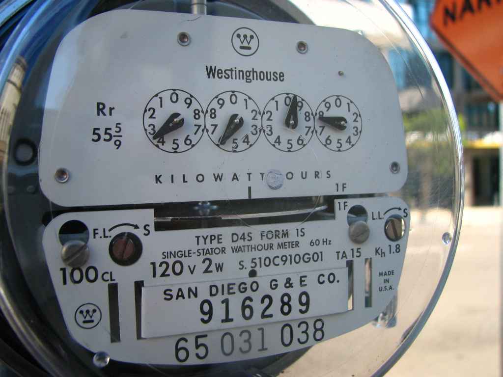
- Take the Bus Rating (the number on the label).
- Multiply the Bus Rating by 120% (The 120% Rule).
- Subtract the main breaker size.
Practice: Allowable Backfeed for a 125A System
- Bus Rating of 125.
- Bus Rating (125) * 120% = 150.
- Subtract the main breaker size of 125 Amps = Allowable backfeed is 25 Amps.
Why Calculate Needed Backfeed?
Understanding the potential backfeed generated by the solar system is essential for determining whether the Main Electric Panel can accommodate it or if a Main Panel Upgrade is necessary. Larger systems create more current, requiring a main panel capable of handling greater backfeed. If it exceeds the 120% rule, a Main Panel Upgrade is needed.
Calculating Needed Backfeed
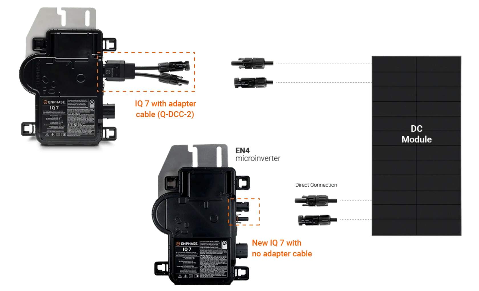
- Max Continuous Output is found on the inverter’s spec sheet.
- Multiply Max Continuous Output by 125%.
- Multiply the result by the number of inverters.
Practice: Main Panel Upgrade Evaluation
Consider a 150A Panel with a 150A bus rating. The allowable backfeed is 30 Amps. Using the Enphase IQ 7 Plus microinverter: Max Continuous Output: 1.21 Amps. Number of inverters: 20.
Alternatives to Main Panel Upgrade (MPU)
Derating
Derating Explained
Derating is a critical technique used in electronics, especially with devices operating below their maximum power dissipation. It considers factors like device temperature and cooling mechanisms to ensure safe performance. When the backfeed exceeds 40A, derating adjusts the Main Breaker’s capacity. For instance, with a backfeed current of 60A, the goal is to recalibrate the Amperage limit to reduce utility power contribution by 20A. Practical derating may involve replacing the original main breaker with a derated counterpart (e.g., 175A).
However, the supply chain landscape’s challenges can hinder derating’s efficacy due to limited specialized components. Innovative solutions are required for successful integration into solar energy systems.
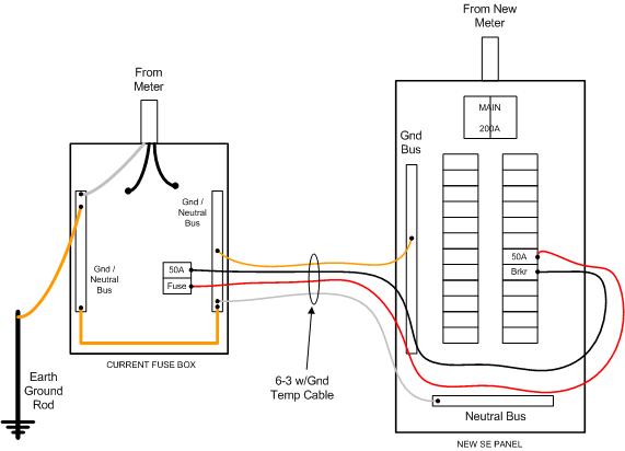
Supply-Side Connection
Supply-Side Connection is an alternative to a main panel upgrade, suitable when accessible conductors exist between the meter and main breaker. This method involves tapping into the line side.
In conclusion, understanding and calculating backfeed is vital for optimizing solar systems and ensuring panel compatibility. Whether through derating or supply-side connections, effective strategies exist to avoid costly main panel upgrades.

Most supply-side connections take place by a “piercing tap connection” to the conductors between the electric meter and the main breaker, and this can be used to back-feed any size system that your customer needs.
Wherever this is allowed by the jurisdiction and utility, this is the first alternative interconnection method that is explored if the system size exceeds the capacity of the main panel.
*The Supply-Side Connection is typically not available in California.
Exploring Load-Side Connection as an Alternative
An alternative to the supply-side connection is the Load-Side Connection, which offers a variety of implementation methods. Unlike supply-side connections, which have fewer restrictions, the point of PV interconnection occurs on the load side of the main breaker. This approach presents unique challenges and opportunities compared to supply-side connections.
In situations where derating or a supply-side connection is not feasible, the load-side connection can prove valuable. It’s particularly useful for connecting large solar systems to smaller service panels. However, its applicability is limited to specific electrical scenarios.
Upon receiving site survey information, the design team will thoroughly explore the load-side connection method as an alternative to a Main Panel Upgrade (MPU).
SUMMARY: Enhancing Solar Integration Through Main Electric Panel Management
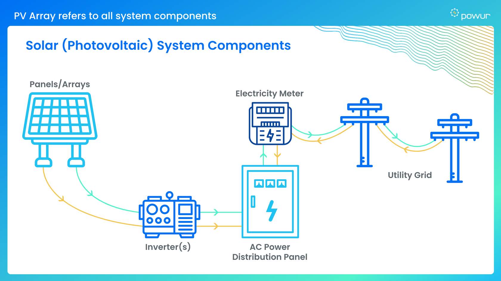
The Main Electric Panel plays a central role in a household’s electrical infrastructure, acting as the primary access point for electricity from both the utility grid and residential solar panels. Its pivotal function involves receiving incoming power and distributing it throughout the home to meet diverse energy demands. A successful transition to solar energy hinges on ensuring the main panel’s capacity to handle the augmented power load generated by residential solar systems.
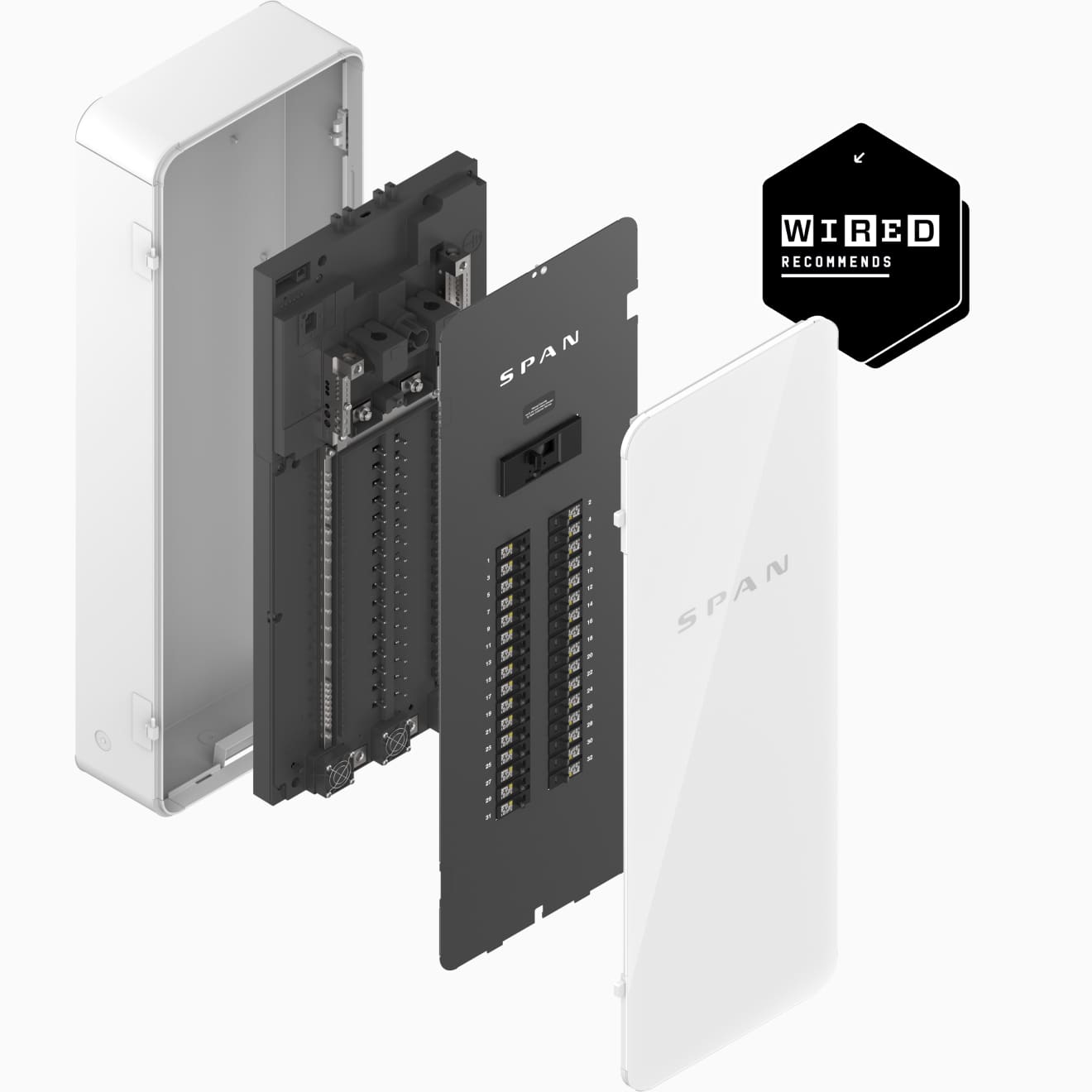
When the existing main panel falls short, the option of a Main Panel Upgrade (MPU) becomes relevant. This involves replacing the current panel with a more robust unit capable of accommodating the increased power requirements essential for a safe and efficient solar setup. The decision to pursue an MPU depends on factors such as the main panel’s rating, adherence to the 120% rule, and analysis of backfeed data provided by the inverter. By conducting simple calculations, it’s possible to determine the necessity of an MPU. However, exploring alternative strategies to address capacity constraints within the existing panel is also worthwhile. The design team can delve into these options armed with insights from the site survey.
Gaining an understanding of these complexities is vital for accurately pricing a customer’s solar solution. This involves accounting for potential MPU costs if deemed necessary, thus preemptively mitigating the need for change orders and fostering transparent expectations from the project’s inception.